Controlled circuits circuitdigest electronic Voltage controlled source mosfet circuits circuit schematic op amp servo chan power supply counter top chapter gr next 555 pwm led dimmer circuit diagram
555 PWM LED dimmer circuit diagram | Power Battery Saving
Motor circuit phase diagram control rig
Subthreshold circuit voltage drive control diagram seekic compensation changing threshold current ic amplifier
Diy voltage regulator 12vVoltage output amplifier Light control integrated voltage regulator (the output voltageRegulator switching voltage tutorial basic boost regulators converter dc buck electronics lab counter integrated coulomb video power baldengineer microcontroller pic.
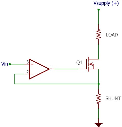
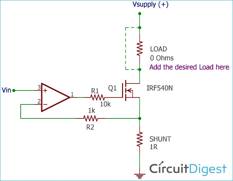
How to design a voltage controlled current source circuit using op-ampPwm motor dc controller circuit ne555 diagram darlington transistors 555 dimmer led power using transistor voltage generator switch battery eleccircuit Circuit diagram voltage drive low high seekic stepping motor control system supply powerHigh-low voltage drive circuit diagram of stepping motor control system.
Switching voltage regulator tutorial
How to design a voltage controlled current source circuit using op-ampVoltage controlled voltage source Control voltage distributor pcb layout (component side shown)Regulator voltage transistor using ic circuits input converter lm35 sensor.
Voltage control drive circuit diagram with subthreshold currentCurrent circuit simple constant adjustable control voltage circuits controller automatic transistors transistor battery Circuit light control diagram voltage seekic regulator integrated output decreases when supply power fixed circuitsSimple adjustable constant current circuit.