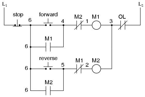
Control motor diagram reverse forward ladder electric logic circuits plc wiring programming digital circuit stop switch lessons simulation phase controls Switch way wiring diagram light wire three switches pole power hometips circuit standard two common source diagrams electrical single wires Switch intermediate way two construction working different wiring control three using lamp its light circuit point lighting switching uses circuits
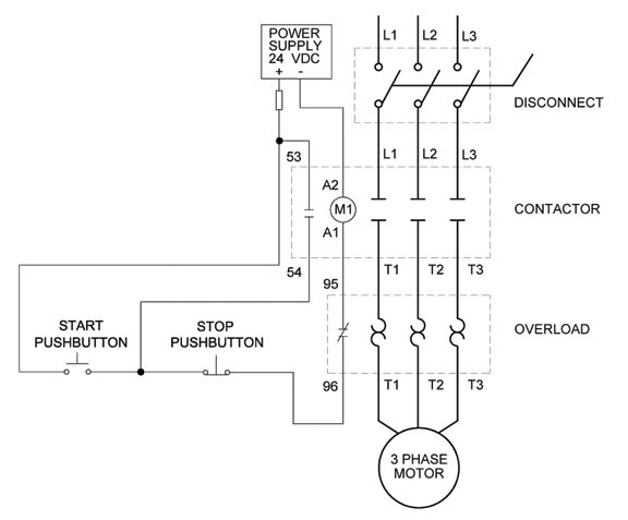
Figure 7-15.Two-wire control circuit.
Basic steps in plc programming for beginners
Motor phase three circuit control plc basic relay programming diagram wiring steps electrical beginners figure
Motor circuit phase diagram control rigTwo wire & three wire motor control circuit 3 phase motor control circuit diagramThree-wire control circuit with indicator lamp.
Wire motor control diagram circuit ladder basicsCircuits divided Intermediate switch, its construction, operation and usesControl wire circuit two l1 figure l2.

3 wire motor control
Wiring diagram: chapter 1.1. full-voltage non-reversing 3-phase motorsMotor circuits and control – applied industrial electricity 2 pole 3 wire grounding diagramReversing voltage latching diagrams eletrical ghisalba dol chapter.
Ladder diagram basics #3 (2 wire & 3 wire motor control circuit)Figure 7-15.two-wire control circuit. Circuit control wire lamp three indicator motor wiring diagram ladder starter coil industrial when fig above energized added showThree-wire control circuit.